"Jumpy" Analog Inputs- Input 53 Speed Reference Filtering

Hi There- my new favorite customer Ryan was looking at a VFD this morning that had a “jumpy” analog input from the building control system.

We see this occasionally where the 0-10v signal from the EMCS is moving around constantly by fractions of a volt, it doesn’t hurt anything— A VFD isn’t like a damper actuator where hunting will wear it out— But in this case the customer didnt like that the display was constantly changing between “running on reference” and “ramping” like it didn’t make the setpoint.

Who knows where these tiny voltage changes come from, but you can smooth them out by adding filtering to the VFD input— See below. Change the default filtering in parameter 6-16 from .001s to around 1s or so and it will smooth out those little bumps. If you set the filtering too high it will slow down the VFD response to actual reference changes.


Programming a Run Status for the VFD

Hello- recently a customer asked me this question: “Is there ever a time where the VFD status can say the pump is on, but the pump actually isn’t running? Whether from a burnt-out motor or any other reason. Will the VFD always recognize that the pump has failed?” (Hi Ryan!)

This is a great question.

In the old days before VFDs, customers would sometimes use current sensing relays (CSRs) to verify that amps were actually flowing through the motor wires, the CSR status gave us an indication that the motor was pulling amps and (likely) rotating. Many smart customers still add these CSRs to VFDs to show status and they have their reasons.

However, these CSRs do need some adjustment- you want them to go high when the motor is pulling a real load, and not necessarily show a run status in the event that the motor throws the belt or is otherwise operating under no-load conditions. The little screw pots in there can be finnicky, and they come in different sizes depending on amps that you need to read.

Can we just use the VFD programmable relay outputs to tell us the same thing? The answer is MAYBE, but there are several options depending on your sequence.

Here is a summary of the options I can think of now, as soon as I publish this I will likely think of more options.

function relay programming

Option 1 (this is typically default from the factory): Set one of the relay outputs 5-40 to "[5] Running”. This tells you that the drive has a start signal and is trying to run the motor.

Advantage: This is easy and its the default setting on most drives. Everybody pretty much knows what this means and it usually works. If we lost a motor phase or had a ground fault the VFD would trip and the status would drop.

Disadvantage: We don’t specifically know that any motor is connected, just that we are asking the vfd to run and it thinks it is running. That is, if the motor throws the belts or is physically disconnected you wouldn’t necessarily know.

Option 2: Set relay output 5-40 to “[6] Running/no warning”. This is a little better version of option 1, just adds the information that we don’t currently have any vfd warnings (high temp or current warnings).

Option 3: Set relay output 5-40 to “[8] run on reference/no warning”. Even more information here, now the vfd has reached the commanded speed with no warnings. If the speed is within 5% of the setpoint then the the relay goes high.

Option 4: Set relay output 5-40 to “[14] above current, high”. Then adjust 4-51 to a current value that is slightly below the current at minimum speed.

Current High display

Advantages: This is now an electronic version of the current sensing relay, the VFD relay will only show a status when the current goes above the typical draw that you see above the motor minimum speed. The motor is probably working and turning a load here.

Disadvantages: The display will read “current high”, it might freak out some owners if they didn’t expect it. It doesn’t actually show as a warning just a message on the bottom of the display. (see pic)

Option 5: Do any of the options 1/2/3 AND program the “broken belt detection” sequence that is built into the VFD. This will give you a “broken belt” warning or trip if the amps are below a preset limit when the drive is running. See my other blog post about how to do "Broken Belt Detection Setup"

Bacnet AV5 Amp reading

Option 6: Do any of the above options AND read the actual motor current value over bacnet— It will show up as AV5 and reads in Amps. If the motor has amps and there are no other alarms reading, that is probably the best that we can do to see if the motor is doing work here.


Note: On VFDs with bypass, if you are running in bypass due to a (hopefully) very rare failure in the VFD— how do we get the motor status? Since this is a rare and temporary emergency operating condition, you may not necessarily need a motor status here. You manually switched it into that condition and it is running full speed—- If you really need a motor status here at the EMCS you will probably need a CSR to tell you that the motor is spinning.

As always, call us if you have any questions!


Switching set-ups with Danfoss VFDs

Rev 10/12/21 This was a complicated request from a specific customer, and will likely be revised several times.

There are multiple exhaust fans that feed common ductwork, and for the sequence they want the fans to “warmup” prior to the exhaust damper opening up to the common duct. They were getting nuisance alarms if the damper opened on run request prior to the motor startup due to the loss of pressure.

In this example we can use the Danfoss VFD ability to “switch setups” to give us a completely different sequence for the VFD depending on whether the damper is open or closed. The damper endswitch will trigger the active setup.

Here are the controls wires:

damperwiring2.jpg

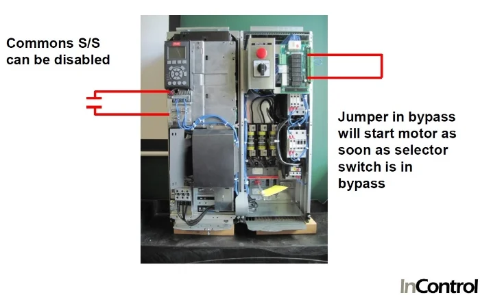
SS on 12/18, Damper endswitch on 13/19 (made when damper is fully open), Damper command on relay 1 (damper open when relay goes high)

Here is the sequence:

Start command received at 12/18 from EMCS

VFD goes to preset speed (example below is set for 15hz)

Relay 1 turns on to drive damper open when motor goes above 401rpm

When the damper endswitch is made to 13/19 then the VFD is under EMCS controls

When start signal is removed, motor will slow down.  Damper will start closing when motor goes below 401rpm, the very slow ramp down time takes effect 180s in the example below.


Programming Steps: 

0-50 lcp copy select [1] “all to lcp” **Copies existing parameters to keypad in case you need to restore them: 

0-10 active setup, verify [1] “setup 1”

Set 5-11 term 19 to [23] “setup select bit 0”  **allows the damper endswitch to change the setup, when its made the drive will go to setup 2

Set 4-53 warning speed high to 401rpm (set this to whatever speed works for you but must be below 4-12 min speed in Hz)

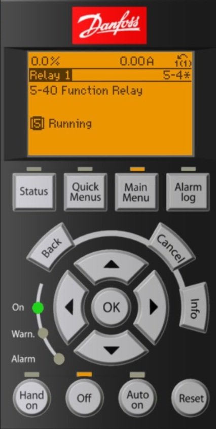
Set  5-40 function relay 1 set for [17] “above speed high”  **activated the damper open command when speed goes above 401rpm

0-12 this setup linked to [2] “setup 2”  **links the setups so you can switch during motor running

0-51 setup copy to [2] “copy to setup 2”  copies these parameters to setup 2


While still in setup 1 (these settings are only for setup 1, not copied over to setup 2)

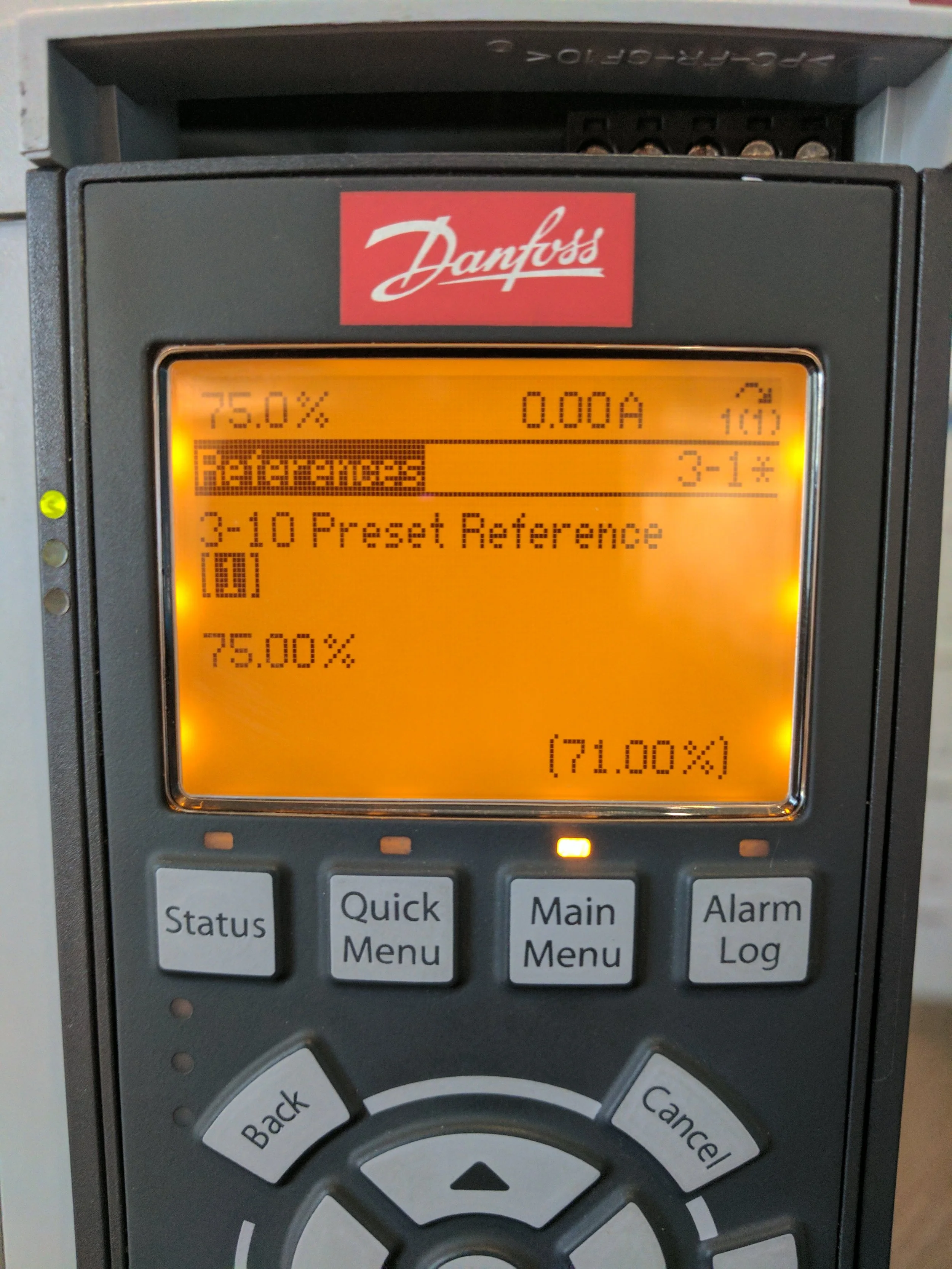
Set 3-02 minimum reference to 15Hz (or whatever low speed you want the VFD to run at when the damper is closed)

Set 3-03 maximum reference to 15Hz (or whatever low speed you want the VFD to run at when the damper is closed)

Set 3-42 ramp 1 ramp-down time for 180s (or some slow speed to ramp down while the damper is closing during motor stop, this will only affect the time from 401rpm to 0)


Change to setup 2

Set 0-10 active setup to [2] setup 2

Set 0-12 this setup linked to [1] “setup 1”

Set 0-10 active setup to [9] “multi-setup” **enables the damper endswitch to switch the setups


Cycle the VFD Power— this will reset the drive after all of the I/O changes that you made previously


Test the sequence to verify that it is working.

When all looks good then save the new parameters:

0-50 lcp copy select [1] “all to lcp”

setup 1.jpg

You can tell that this vfd is in “setup 1” because the 1(1) in the upper right hand side of the keypad.

Setup 2.jpg

This vfd is in “setup 2” currently

Danfoss VFD Skip Frequencies

Hello- One of our favorite campus customers (Hi Chris!) called today and was asking about how to avoid certain “resonant” frequencies in their mechanical system.

Basically, there is a nuisance vibration from the ductwork at around 51-52Hz, is there a way in the VFD programming to fix it?

The answer is yes!

Danfoss VFDs provide up to 4 “bypass” frequency bands that you can program to avoid different speed bands that are in the operating range. The VFD will accelerate through those bands using the rampup/rampdown speeds programmed, but will not linger at those speeds. This can help avoid those nuisance vibrations and noises.

Here is an example:

Bad Mechanical Frequencies: 51-52 Hz

Start the Bypass at: 50Hz

End the Bypass at : 54 Hz

Program 4-61 [0] “Bypass Speed From” to 50Hz

Program 4-63 [0] “Bypass Speed To” to 54 Hz

  • Note that this is an “array” point, there are 4 different arrays that you can program. The [0] in the example above shows that it is the first array item programmed, you can add others later if needed. There are arrays 0,1,2,3 available in this point that would make 4 different ranges for bypass speeds.

See pictures and manual sections attached! Pls call us if you have any questions.

20210407_140801.jpg
20210407_140836.jpg
bypass.jpg

Outside Airflow Measurements and Covid- Two projects (One for "right now" and one for "later")

We have had a few calls from customers lately, especially school customers who are trying to comply with outdoor air requirements to bring students back.

Here is a sample of some of the basic requirements: https://www.epa.gov/iaq-schools/epa-supports-healthy-indoor-environments-schools-during-covid-19-pandemic

One of the customers is running around with portable meters and trying get spot-measurements on outside air.

The problem with a spot measurement is that it doesn't take into consideration the varying conditions after the measurement- economizers, linkages, building pressure, occupancy changes, heating vs cooling etc.

This Ebtron airflow measurement station stays IN the ductwork for accurate and permanent monitoring: https://ebtron.com/wp-content/uploads/GTx116e-PC_Overview.pdf

GTx116e.jpg

The Ebtron transmitter has both analog outputs and optional data-logging, so you can verify continuously on the display or from your PC that you are meeting OSA requirements for your site.

For a quick-project: put an Ebtron airflow station on the gyms/libraries/commons/classrooms, stand-alone with data-logging to verify clean-air dilution.  You can have the station quickly and they only need 24vac power.

In the longer term: connect the stand-alone Ebtron airflow stations to the BMS for continuous monitoring and alarming.

Viewing the status on Danfoss VFD inputs

InputStatusScreen.jpg

Hello- A customer recently asked about how to view the status of the inputs on a Danfoss VFD— Are they on or off? Here is an easy way to check using the display.

Navigate to parameter 16-60 “Digital Input”

The display is binary, showing the status of all the inputs at that moment. Zero means the input is “off” and a one is “on”.

To tell which digit is for which input, you have to use the chart below from the programming guide.

Input 18 is typically used for the Start/stop, according to the chart input 18 is “Bit 5”, AND YOU COUNT FROM THE RIGHT STARTING WITH BIT 0.

In summary, input 18 is going to be the sixth zero from the right if that makes sense. See the picture below.

As always, call us if you have any questions.

Digital Inputs 1660.png

30 minute technician training- Ebtron, Onicon, Danfoss, TSI, Sage, MSA, Acutherm

Hi- Tom, Rick, and I have been working on a series of 30 minute Zoom presentations for technicians— basically the bare minimum that you need to know to setup our equipment. They are different depending on the product but they typically include the following:

20201022_125932.jpg
  1. Basic Installation

  2. Initial setup

  3. Analog output/input scaling

  4. Communications

  5. Basic Troubleshooting

We tried to keep them to 30 minutes, and setup so you can watch them over your phone or laptop. I still like to do these live— we may record them in the future but live is easier to make sure we get your questions answered.

Don’t let the fact that they are live keep you from scheduling a session! We literally have nothing better to do than train customers on our equipment, and we will absolutely run this for 1 person no problem (you don’t need a group).

Training is always free for any customers or owners, just let us know. We have these already setup for Ebtron, Danfoss, Onicon, TSI, Sage, MSA, and Acutherm. The other equipment is coming so let us know if you need something! TimH

Danfoss VFD Broken Belt Detection

A customer wanted to show a “run” status from the VFD, but wanted to drop the run status if the current went below a certain threshold— this is sometimes known as “broken belt detection” where if the motor throws the belt and isn’t doing any work, we can get an alarm and drop the run status.

20201013_081654.jpg

Some clients do this with an adjustable current sensing relay on the motor output wires, but these are sometimes finicky and require a manual screw adjustment.

If you want to do this on the VFD, here are the points that you should program:

22-60 “Broken Belt Function” set to [1] Warning

22-61 “Broken Belt Torque” set to 10%— this is the default, you may need to adjust this later

22-62 “Broken Belt Delay” default is 10s, I would set this to whatever the motor ramp up time is in 3-41 to give the motor time to ramp up to speed— maybe 30-60s depending on the motor. This will help avoid nuisance warnings while the motor is ramping up to speed.

5-40 Relay1 Function Relay set to [6] Running no Warning— this will give you the run status that you want, then drop if ANY warnings or alarms come in, including our broken belt warning W95. Set this to any of the outputs or relays that you want, I just use relay 1 as the example here.

0-21 Display line 1.2 set this (maybe temporarily) to [1622] Torque %. What this does is display on the top middle of the screen what the torque percent of the motor is at that moment. If you ramp the motor up and down you can watch this % change, then you want to set 22-61 a little BELOW the typical normal value of motor torque so that it will trip. Watch it under a few different load conditions and speeds and see what the normal values are.

Ebtron Probe Installation Video

Hi- Ebtron recently released a nice video on how to install insertion type probes- the most common type to install in ductwork.

Here is the link: Ebtron Probe Install

The most common question we get is about probe spacing for multiple probes, that is covered at the 1:48 minute mark.

As always, don’t forget that we measure and mark the ducwork for free, so that they probes are in the best possible location for accuracy and servicability. NO CHARGE to come to the jobsite!

TimH

VFD sizing and NEC table 430-150

Hello- a client recently asked about VFD sizing for motors- here is a quick explanation.

In general, Danfoss VFDs are sized to make sure that we slightly exceed the max amp values in NEC table 430-150, see an excerpt below.

That NEC 430-150 table tells us:

  1. The MAXIMUM amps that are allowed for a given HP motor (see 7.6amps for a 5hp/460v motor). Most modern high-efficiency motors will be less than this max value by 10-30%.

  2. Low RPM motors may need MORE amps then specified on this table— the table is for standard 1800rpm motors. If you remember your high school physics (heh!), HP = Torque x RPM. Since the RPM is lower, you need more torque to get the same HP. To get more torque you need more amps from the VFD. We see low RPM motors sometimes on direct-drive fans. Verify the motor FLA on low rpm motors before ordering.

  3. Multi-motor applications may need to bump up one VFD size to accommodate the amps— To drive two 5hp/460v motors needs 7.6a + 7.6a = 15.2amps max. If you look at the 10hp/460v value in the table it is only 14amps max. In this example we may need a 15hp VFD to run those two 5hp motors.

In summary, we frequently use Table 430-150 for budgeting, but you should always use the motor FLA from the dataplate to be sure that the VFD is sized appropriately.

ALWAYS USE THE MOTOR FLA TO VERIFY THAT THE VFD IS THE CORRECT SIZE!

NEC+excerpt.jpg
DanfossVFDsizes.jpg

Motor Spinning Backwards or forwards when the VFD is off

Hi- Part of the VFD startup process is verifying the motor rotation is correct when the motor is running on the VFD AND in bypass. If you need help with this pls see the manual or call us.

Sometimes a customer calls about a motor that is “freewheeling” backwards or forwards when the drive is off. This happens if a fan is connected to a common plenum and is air is being sucked past it, causing the motor to rotate.

This doesn’t hurt the drive but can cause other problems-

  • The VFD can trip on overcurrent as it tries to “catch” a motor spinning backwards at high speed during startup.

  • Equipment that is still moving but commanded off can cause other problems or safety issues for the operators.

There are a couple of points to check here:

  1. Set parameter 1-73 Flying Start to [1] “Enabled”. The VFD will test for a rotating motor prior to starting. If needed it will slow it down and start spinning the correct direction, avoiding motor overcurrent. This function adds about 10 seconds to the startup process.

  2. Set parameter 1-80 Function at Stop to [1] DC Hold/Motor Preheat. Then set 2-00 current percent to the lowest value that will hold the motor. Start low and work your way up, excess current adds heat to the motor and wastes electricity.

HoldSpinningMotor.jpg

Using the Jog Mode on Danfoss VFDs

Hi- A customer recently asked about having a VFD go to a preset speed from a single input, that would pre-empt the speed the drive is being commanded to normally. An example is a exhaust fan that typically ramps up with building pressure, but should go to full speed on a local command from a fire panel or other gas sensor.

This jog mode can also be used in cases where you only have a single input that you want to use to start the motor AND go to a preset speed (no other speed reference is required).

This is different than putting the VFD into “fire mode”, which ignores all alarms and runs the VFD until it burns up— sometimes the sequence doesn’t need that and you want something simple. Jog mode still monitors the safeties and alarms from the vfd and will trip if limits are exceeded.

After the drive is started and running- typical s/s signal on term 12/18 and speed ref on 53/55. You can add the “jog” signal to terminal 29 in this example. (on some new drives terminal 29 may be defaulted to “jog” already)

Set 3-11 “jog speed” to the speed you want the vfd to run

Set 5-13 terminal 29 to [14] “jog”

At that point, a contact closure between 12/29 will put the drive into jog mode and run at the jog speed.

As always, call us if you need any help.

20191004_100242.jpg

Ebtron Analog Output Scaling and Testing

Hi- A customer was asking about analog output scaling for Ebtron transmitters— Here is a good place to start:

  1. Probe based airflow stations come default as 0-5000 feet per minute (FPM) on the analog output 1 from the transmitter . Note that this is a VELOCITY and not a VOLUME.

  2. Fan inlet airflow stations come default as 0-10,000 FPM since they are generally a faster speed into the inlet cone.

  3. For most systems, we recommend that you bring all of the transmitters velocity analog output (either 0-10v or 4-20ma based on the dipswitch) into your control system Analog Input (AI) as the same analog scaling— that is, regardless of duct size all of your Ebtron probe transmitters will have the same 0-5000FPM scaling into your AI. We like bringing all of the transmitters in with the same scaling to avoid field confusion— at least initially.

  4. Take each AI and multiply it by the duct area to get an AV showing the VOLUME in CFM.

    VELOCITY x DUCT AREA = VOLUME FLOW

    Having the volume flow be an AV allows you to do other operations on it later that you cant do with an AI*. We can lookup the area from the packing slip if you don’t have it— call us if you need this value.

    *Useful AV operations: You can write a “0” to the AV on a windy rooftop when the unit is off, so there aren’t any weird airflows on the screen to distract the operators.

Here is a math example-

If you brought the 0-10v signal in as 0-5000FPM on a 4’x4’ duct:

5000FPM x 16Ft^2 = 80,000CFM at max flow. This means that 5V at the transmitter should show 40,000CFM on your EMCS display.

Here is how the manual describes it, we did the “manual conversion”:

GTC-116 manual description

GTC-116 manual description

20190513_142253.jpg

USING THE TESTOUT BUILT INTO THE TRANSMITTER:

Ebtron gave us a great tool to help commission this- by going into the setup/tools menu you can force the output to a certain %, and verify that we did all of the steps correctly. If I command the output to 50% I can measure 5v on the output and should see the EMCS display change to 40,000CFM in the above example.

As always, please call us if you have any questions.

Bacnet and Digital Inputs for VFDs

8-01 parameter.jpg

A customer called today and was asking about a VFD that would only start AFTER a power cycle, run for a while and then would stop.

They were starting the drive with a contact closure on digital input 18, but also connected over bacnet.

In these cases where both comm and hardwired points are connected, it is possible to get multiple start or stop commands conflicting that result in unreliable start/stop behavior. This happens when the bacnet BV start point is placed on a graphic or in the schedule, while the BO is also scheduled or commanded.

Here is how you can fix this:

If you are ONLY going to start the VFD using the hardwired point:

Set parameter 8-01 “control site” to "[1] Digital Only”. Now bacnet commands to start or stop the drive will have no effect, only the hardwire digital point will work.

Saving and Copying VFD Parameters to the Keypad

Copying TO the Keypad

Copying TO the Keypad

In Progress

In Progress

Copying FROM the Keypad into the drive

Copying FROM the Keypad into the drive

Hi- Today a customer was asking how to copy and save Danfoss VFD parameters to the keypad.

This process is very useful as a fast way to program drives— say that you have 1 vfd setup the way you want, and you want to copy those parameters to all of the other vfds exactly.

Heres how you do it:

1. Parameter 0-50 LCP Copy set to [1] “All to LCP”

The “LCP” is Danfoss jargon for the keypad, this saves all the existing parameters TO the keypad

2. Remove the keypad by tilting down from the top, install keypad in the drive that you want to program

If the new drive is the same size as the saved drive then:

3. Parameter 0-50 set to [2] “All from LCP” Takes the saved data FROM the LCP into the drive

If the VFDs aren’t the same sizes:

Parameter 0-50 set to [3] “Size indep. of LCP” meaning that all the parameters except the motor data will be sent to the new vfd. You will have to program the motor info (Motor FLA etc) manually.

Make sure to check the motor rotation and other startup checklist items, this is just a quick way to get the parameters entered.

Danfoss VFD "Common" Start/Stop

Hi-  Recently a colleague asked about "common" start/stop for VFDs that have the integral bypass--  Basically, the drives come wired with the ability for a single start/stop signal to start the motor when the SELECTOR SWITCH IS IN EITHER DRIVE MODE OR BYPASS!

The reason that you would want common s/s--> It allows the operator to select bypass and the motor will NOT take off at full speed, without dampers/valves etc being positioned in the correct place.  Motors running at full speed when the system isn't ready have the bad effect of blowing out ductwork and dampers.   When selector switch is in bypass you MUST also have a s/s from the EMCS as a backup to make sure the system is ready to start.

The reason that you DON'T want common s/s-->  You want operators to be able to select bypass in an emergency, and want the motor to run immediately without any other control signals required.

Below is a picture showing the examples, as well as a section from the manual on how to change it-- WARNING- the manual excerpt says that you should cap off the "red" wire after jumping X55 3/4, that Danfoss wiring is probably blue from the factory.  See the final picture for how it should look in the panel.

Common START/STOB ENABLED

Common START/STOB ENABLED

COMMON START/STOP DISABLED

COMMON START/STOP DISABLED

manual common ss.jpg
BLUE DANFOSS WIRE FORMERLY CONNECTED TO TERMINAL 18, WIRE NUTTED OFF WITH CONTROLS SS NOW ON 12/18.

BLUE DANFOSS WIRE FORMERLY CONNECTED TO TERMINAL 18, WIRE NUTTED OFF WITH CONTROLS SS NOW ON 12/18.

Monitoring Danfoss VFD in "Bypass"

IMG_20171004_084854.jpg

Hi!  Recently a customer asked about a way to tell remotely if a Danfoss VFD was in bypass-  there are probably several ways to do this but here are a couple methods:

1.  Wire the EMCS point to X56 5/6

On 3-contactor bypass drives (ask us WHY we recommend and sell 3-contactor bypass), Danfoss gives you a customer connection board in the bypass section that allows you to monitor the bypass contactor directly.  You have to hunt for the board a bit, on different sizes drives it is in different places but they usually look similar:  a couple rows of small green terminal blocks.  Find the X56 terminal block that has 12 terminals, a contact between 5/6 indicates that the drive is on bypass (see picture and dwg).

This works if your intent is to show that the drive is on bypass.  If you want to show that the drive is "not ready" for ANY reason (major alarms, power failure, disconnect off, fuses blow, OR selector switch in bypass) then try method #2.


bypass connections.jpg
IMG_20171004_084932.jpg

2. Wire the EMCS point to Relay 2 NO (4/5). 

Program Relay 2 parameter 5-40 to [160] "no alarm".  The relay will go high and have a contact closure between 4/5 if everything is OK with the drive.  Contact would be open if power failure, bypass, or alarm.

-or-

Program Relay 2 5-40 to [3] "Drive Ready/remote control"  Does the same as above but contacts open if the drive is placed into "manual" control from the keypad.  Might be useful if you are concerned that operators won't return the drive to auto mode-- might be a nuisance alarm if they do manual control a lot.

*Final Notes:  Unfortunately the bypass status can't really be a bacnet point, because the point of a bypass is to take over if there is a critical failure in the drive (and it wouldn't be talking bacnet at that point).  There are "electronic" bypasses that continue to talk while in bypass BUT we like the simplicity of a 3-contactor old school bypass when you need it -- don't add complexity to your backup emergency option.

Running motors ABOVE 60Hz

Traditionally, maximum motor speed has been 60Hz for motors controlled by VFDs.  Sometimes, it is necessary to have a higher upper frequency limit.  Danfoss VFDs can run at output frequencies higher than 60Hz.

This is especially useful if you are just a little bit short of water/air at full speed, but the motor is still running below its nameplate full load amps (FLA).

No matter what-- you don't want to run the motor above the FLA, and you may want to confirm that mechanically it is OK (motor/fan/pump/belts) to spin faster in your application.  The VFD doesn't care as long as you are below its rated outputs.

Here’s an example of changing the maximum output frequency from 60Hz to 75Hz.

To change the maximum frequency output on the VFDs from 60Hz to 75Hz, update the following three parameters:

3-03       Maximum Reference = 75Hz

4-14       Motor Speed High Limit (Hz) = 75Hz

6-15       Terminal 53 High Ref/Feedback Value = 75Hz --- or whatever input you are using for the speed reference.

After you make these changes to the limits, slowly walk the speed up to the max in "Hand", making sure that the motor amps don't exceed the nameplate FLA.

Danfoss VFD Preset Reference Array

Sometimes you want to control a VFD with multiple digital outputs, instead of using a 0-10v or 4-20ma analog speed signal.

Danfoss has a couple of ways to do this:

1. For one preset speed, you can use the "jog" function in the VFD.

Set parameter 5-11 Term 19 (or any open input) to [14] Jog.  When you turn this input on, the drive will automatically go to the speed that you have set in parameter 3-11 Jog Speed--this will happen regardless if you have a regular s/s turned on.

2. For multiple speeds (like a low/high exhaust fan at a potato chip factory- Hi John!) you can use the "preset reference array" giving you up to 8 speeds with just 3 digital inputs.

Set parameter 3-04 to [0] "sum"- basically adding all of the input, external and preset references.

Set parameter 3-10 "preset reference" values-- remember this is an "array" with up to 8 different values.  In the example below we set "preset ref 0" to 30Hz (50%), and "preset ref 1" to 45Hz (75%)-- these are the two speeds that we want the drive to run in this example.


Set 5-11 Term 19 (or any open input) to [16] "ref bit 0" 

When the S/S is received, the drive will ramp up past the min speed to 30Hz, if you turn Input 19 on then the drive will speed up to 45Hz.  You can see that if you added 2 additional inputs you could get access to all 8 different speeds per the matrix below--- just by turning on and off the 3 input points.  As usual call us if you need any help here.

If you just want to activate the speeds with the reference bits only (no separate start/stop input, the drive only runs when you have a speed reference on it, otherwise it stops)

  1. Setup the preset reference array like above.

  2. Test your speed commands by jumpering the reference array inputs, you should see the reference values change.

  3. JUMPER the start/stop so it is always on

  4. Set parameter 1-82 “min speed for function at stop” to be just slightly higher than the minimum motor speed. For example, if the min motor speed is 12 Hz, make 1-82 13Hz. That way, when there are no other references commanded on the drive will go to sleep when it drops below 15Hz.