Danfoss VFD Relay Delay Settings

Hi-  A customer has an isolation damper tied to a relay on the VFD, so that when the VFD is started the relay will open the damper.  When the damper endswitch is made, the signal goes back to the VFD to allow it to start.
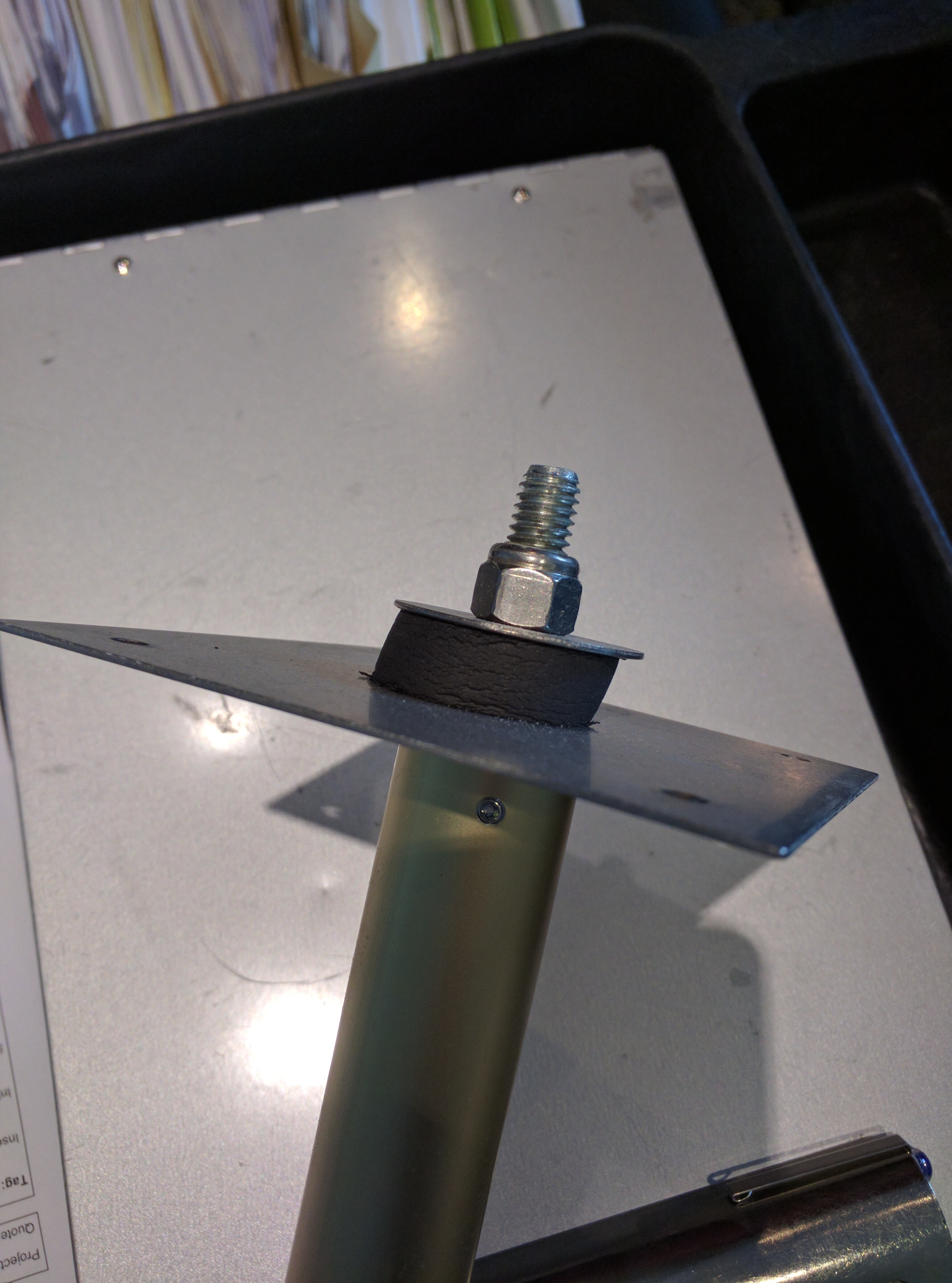
It looks like this:


Use the following points:

Set 5-40 relay 1 to [167] "Start Command Active".  This works great for isolation dampers because the drive can open the damper with any start command or local hand operation.

Set 5-11 Terminal 19 (or any open input) to [52] "run permissive".  If you tie a damper endswitch to that input, the motor will not start until there is a contact closure across the input.

Here is the secret sauce:  When the VFD receives a "stop" command, you may not want the damper to close immediately while the fan is still winding down-- you might trip a pressure switch or otherwise damage equipment if the duct is closed while fan is still turning---

Set 5-42 Relay 1 Off Delay ---Set this to a long enough time to allow the motor to completely wind down before damper closure--- it should be at least as long as ramp down time in parameter 3-42-- probably add another 30s or so on top of that and test it.

As always call us if you have any questions!  

Testing Alarms in Danfoss VFDs

Hi-  Recently a customer asked about how to test alarms-- they wanted to commission the system and verify that VFD alarms are being seen at the front end.

We can use an open digital input, and program the vfd to think that there should be a jumper there-- typically used for a smoke detector or freezestat---no jumper means that the VFD would go into alarm.

Here is one way to do it:

1.       Verify Input 29 has no wires connected to it, if so pick another open input.  We used input 29 in this example because it is usually open in both bare drives and drives with bypass.

2.       Change parameter 5-13 “Digital Input 29” from [14] Jog* to [7] External Interlock.   *It might also be currently set for [0] no operation, that’s fine the point is that input 29 isn’t currently being used and has no wires connected to it.

3.       After you hit OK, the drive will immediately go into “Alarm 60, External Interlock”, and the motor will stop.  This alarm is usually used for external devices--smoke detectors or freezestats and would have to be jumpered to stop the alarm from happening.

4.       Verify that the alarm annuciates correctly at the front panel etc.

5.       Set parameter 5-13 setting to [0] no operation.  The VFD alarm should clear.  If it doesn't clear after a few seconds push the reset button on the VFD.  This just means that your parameter 14-20 Reset mode isn't set to automatically reset after the fault clears.

See Video Below


Onicon's New Isolated Analog Outputs on Turbine Meters

Onicon recently update their turbine meter line, to include some nice digital features.  

Among the goodies:

1. The ability to "flash" meters in the field, including changing pulse rates, pipe sizes, and analog output scaling.  This makes it a lot easier to fix things with limited disruption to your project--- like if the actual flow rates are way higher than you expected and are pegging the output at full scale!

2. The F-1210 now includes an isolated analog output, where the signal common and power common are not connected.  This can be a benefit in some installations where you are trying to isolate electrical noise, keeping the power common off the signal common is a typical remedy.

But what if you are replacing an old F-1210 meter (3-wire connection) with a new one that has 4-wires and you don't want to pull another wire?  Its fine to connect the commons at the meter junction box, see pictures.  This also works for F3500 meters as well.  

For new installations, try to pull at least 4-conductor if you can so you have the choice to keep the signal common isolated.

As always please call us if you have any questions.

TSI Nurses Station Monitor Addressing

The NSD8 Nurses Station is a really nice accessory if you have multiple room pressure monitors.  It allows central monitoring of all of the pressure sensors in that area via a TSI network, separate from the building controls system.

This limits nurses access to other areas, and duplicates the room interfaces that they see when you are in front of the monitored room.

We recently had a question about how multiple rooms are displayed on the NSD8, if you are connecting to a RPM20 that has several pressure sensors.

The NSD8 pulls in all of the pressure sensors attached to each RPM20, in the order of the "nurse address".  Again, this duplicates what they see at the rooms, so if there are rooms you want excluded from the NSD8 then you should leave the RPM off the nurses station network.

See the picture for how the rooms are ordered on the display.

Configuring Totalizer Pulse in ONICON F-4200

This video shows the step-by-step process for changing the value of each pulse.  Keep in mind the meter will automatically limit the pulse weight selection based on the flow rates.  It will not let you select resolutions that are too large or too fast.  Most of the meters are set up as KGAL.   Below is a quick reference for typical settings.

Totalizer Scaling: +KGAL

Resolution:

0000000x = 1000 Gal/pulse

000000x0 = 100 Gal/pulse

00000x00 = 10 Gal/pulse


Totalizer Scaling: +Gal

Resolution:

0000000x = 1 Gal/pulse

Danfoss VFD Analog output scaling

We had a recent request about using the analog output on the VFD. This is the analog output at terminals 42/39 (42 is the output, 39 is the common).

A couple of notes:.

  1. It is ONLY a 0/4-20ma output, there is no selector switch to change it to voltage.
  2. Depending on which output parameter you select, those values will be either output as 0-20ma or 4-20ma, there are selections for both. 

    An example is [107] Speed is 0-20ma, [137] Speed is 4-20ma

  3. You can select what parameter you want the output to follow using parameter 6-50, here are some of the more common ones:
  • [137] Speed 4-20ma, scaled from 0 to whatever the speed high limit in par 4-13, usually 60Hz
  • [133] Motor Current 4-20ma, scaled from 0 to "Inverter Max", should be motor nameplate FLA but you can verify it from par 16-37.  This would be different for different motors of course.

Please call us if you have any questions on how to use the analog output.

Danfoss Warning 34 Fieldbus Fault

Warning 34 won't hurt anything.

It usually comes up during startup, if the VFD has an communications option card (bacnet) and no communications connected.

After a couple of minutes without communications, you will get "Fieldbus Fault W34", a comm failure on the card.

It has no effect on the operation of the VFD, but if you want it to go away you can do one of 3 things:

1. Connect your bacnet comm (with some bacnet traffic).

2. Power off the vfd and remove the card, restart the drive.  It will tell you that there has been an "option change", clear that alarm and you should be fine.  This works if you are never going to use the card.

3. Change function 8-02 "control source" from Option A to "none".  That way the vfd won't look for control comm from the card and the warning won't come up.

The intent of warning 34 is that if you lost communications on the card you could trigger certain events-- stop/full speed/preset speed-- things you might want to do if comm went down and you lost control of the VFD.  Call us for more info you want to run a sequence like this.  

Danfoss VFD Fire Mode

Call us for help before you try this—seriously.

 Danfoss VFDs have the ability to program an input as a “fire-mode” input—meaning that the drive will ramp up and continue to run regardless of any alarms.  Some people call this “run until destruct” mode. 

This is most frequently used for things like stairwell pressurization fans--- where you don’t want too much pressure that would keep the stairwell doors from opening, but enough pressure to keep the fresh air flowing into the stairwell so people can evacuate.  You want the VFD to ignore all the internal alarms and keep the air flowing as long as possible.

 As you can imagine there are some risks to this, most likely is that during routine testing of this feature that the VFD could be forced to exceed the programmed safeties and cause equipment damage—use caution here!  The manufacturer can’t warranty a VFD that has been overloaded or damaged by fire mode testing. 

 Here are some of the points that are useful:

 24-09 Fire Mode Alarm Handling

Set this point to [2] “trip at all alarms-test” during setup and testing, this will keep you from damaging the VFD or motor during testing

Change to [0] “trip and reset at critical alarms” ONLY when you are ready to arm the system for tenants

 5-11 Digital Input 19 (or pick any available input)

Set to [37] “fire mode”, a contact closure on this input puts the vfd into fire mode

 24-00 Fire Mode Function

Set to [1] “Enabled”

 24-05 Fire Mode Preset Reference

Set this to the value that you want the fan to run—usually the balancer will tell you this value based on pressure measurements from the stairwell

 You can also set a reference to come from an analog signal, call us to help set this up.

Here is an excerpt from the Programming Guide that describes fire-mode:  LINK


Danfoss Terminal Blocks

We occasionally get questions about how the Danfoss low-voltage terminal blocks work that are on the VFD-- these are the ones mounted under the keypad on the drive.  There are two variations that are both "spring-type" terminal blocks but the way that you release them is different.

See pictures--

For the older style use a flathead screwdriver in either the top or bottom slot (depending on which wire-hole you are using).  Push in until the spring releases and you can insert or remove the wire.

For the newer style use a flat screwdriver into the flat spot IN BETWEEN the wire holes.  Push in and both holes will recess and you can release or insert the wires.

Ebtron Probe Adjustments

InControl will be happy to measure and mark the mounting locations for all of our airflow stations-- we do it for free and strongly encourage it.  That way you know that you have the correct size and the best mounting location to make sure we get the full accuracy of the device.

There is some mounting flexibility in the brackets, depending on the installation type:

For internal brackets, approximately +/- .75" by adjusting the set screw on the mounting feet.  DON'T OVERTIGHTEN the screws on the feet, especially on the cable end.

For insertion mount, the probes are cut full size but there is a 1.5" stud on the non-cable end that allows for some adjustment.  About 1", especially to make the probe fit a LARGER duct than measured.

For standoff mounts, the brackets need to go straight back to the damper frame, there isn't much flexibility on these.  It would be best to get these right on or slightly larger than the damper opening.

Insertion Mount Installation

Internal Mount Installation

Standoff Mount Installation


Ebtron internal mount feet

Ebtron internal mount feet

Ebtron insertion mount stud-end

Ebtron insertion mount stud-end